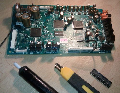
In the previous part we've already established that the op-amps in the DB1080 are sub standard, so they will be replaced with better ones. I will replace them with the NE5532 op-amp of which i happened to have a bunch laying around.This is quite a difficult job because the op-amps are placed on the main board and the only way to access them is to disassemble the entire unit. Last but not least we have five SMD op-amps to replace on the digital board, which sucks because there are a lot of capacitors in the way and of course because SMD soldering is difficult enough as it is.
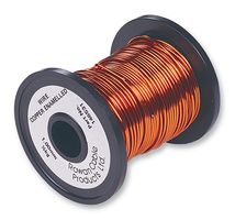
| Things you need | | | | | Enamelled Copper Wire (2mm) | | | | |
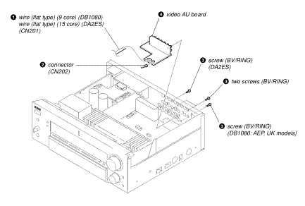
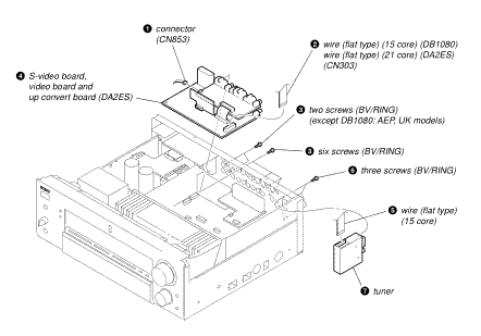
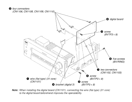
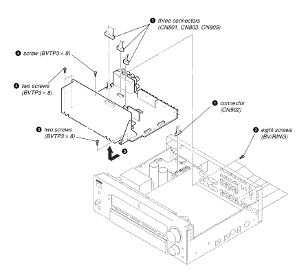
DisassemblyRemove the cover and follow the disassembly diagrams. Keep screws together with the parts they came from, you can loosely put screws back in the connection terminals if you like or use zip bags.
Special care is needed on the digital board. First undo all the screws, backplate and bracket. There are two connectors on the bottom which unplug sideways. There are a lot of capacitors in the way and you'll have to use a quite some force to get them loose. Use a large flathead screwdriver and put the head behind the lip of the connector, then press sideways carefully.
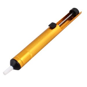
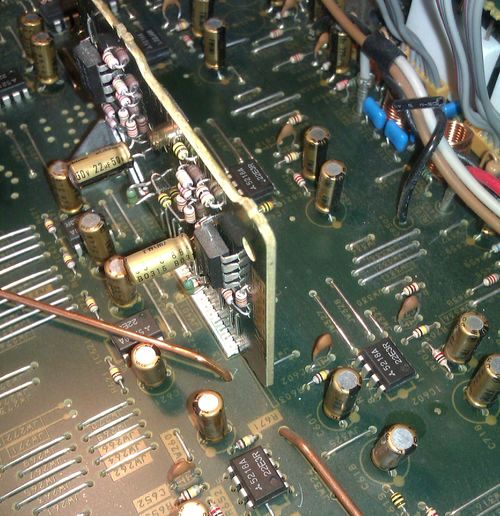
Desolder all the PDIP op-amps from the underside of the main board with the desoldering tool.
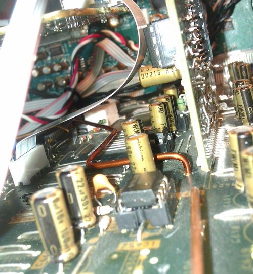
- Desolder the jumper wire (JWH107) that runs over IC621. I personally like to keep an option open for future upgrades so i used sockets instead of directly soldering the new op-amps in place. This upgrade requires a new jumper wire that moves around IC621.
- Put the main board upright with the heatsink up so it rests on the connectors (protect them with foam).
- Desolder IC752 & IC753, this is tricky because the desolder tool can't be properly positioned. Take your time on these.
- Remove all the old op-amps from the main board.
- Clean all the holes where the old op-amps sat, so that the new op-amps or sockets can be put in without any difficulty.
- Solder the new op-amps/sockets in place with the first pin of the op-amp or socket pointing to the designated markings.
Optional Form the new jumper wire out of the 2mm enamelled wire so you are able to access the op-amp and solder it in place.
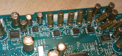
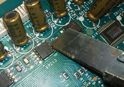
Op-Amps (Digital Board)Now things will get difficult, we'll have to work on the digital board and replace the SMD op-amps.
Bend the capacitors to the side so you'll have more space to work on the op-amps.
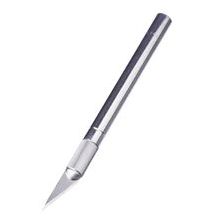
Carefully cut the pins of the old op-amps with the precision knife. Keep the knife at a low angle and low pressure so you'll have less risk of damaging the board. Take your time and if needed a break.
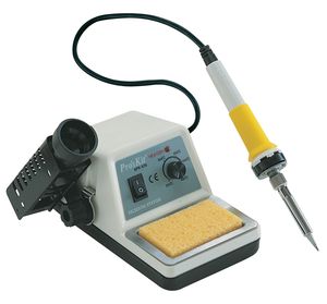
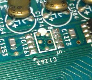
- Once you have cut the old op-amps loose, remove them and use your soldering iron to remove the pins left on the board.
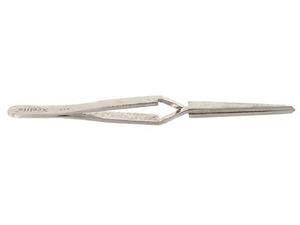
- Place the new op-amps on a flat surface and grab one with the cross lock tweezers.
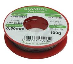
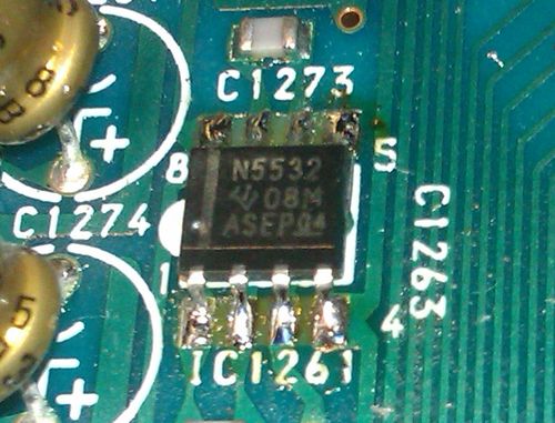
- Position the new op-amp and hold it in place with one hand and solder one of the pins with the other. If the solder joint won't hold, add a dab of solder to the pad and try again.
If you are satisfied with the placement you can solder the rest of the pins with a dab of solder.
- Repeat the previous two steps for the other 4 op-amps.
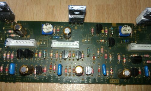
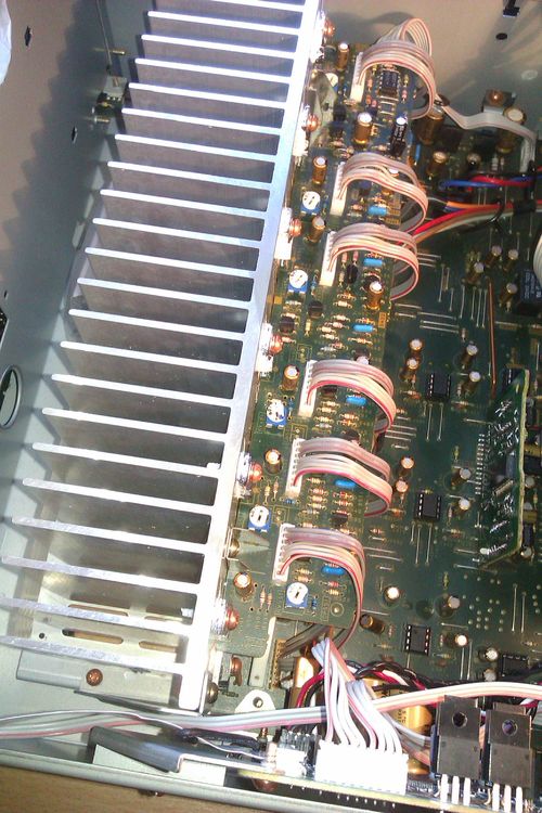
Amplifier Bias circuitThe quiescent current on the DB1080 is set at the bare minimum to increase the lifespan of the output transistors. Sony however was kind enough to provide a bias board that can be used with a fixed or a variable quiescent circuit. To convert the board to a variable setup we need to remove 6 resistors and install 6 new resistors together with 6 trimpots. - Detach all the wires connected to the mainboard.
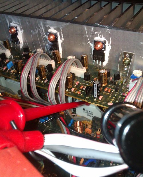
- Remove all the screws from the transistors then the last two screws that fix the board to the heatsink.
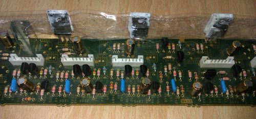
Prepare a peace of plastic wrap to cover all the transistors, remove the board and cover the transistors so that you won't get thermal paste everywhere.
- Desolder R533, R583, R433, R483, R633 and R683 from the board with the desolder tool.
- Solder 680 ohm resistors (metal film, 1/8W) in place at R631, R681, R431, R481, R531, R581.
Solder 500 ohm trimpots in place at RV631, RV681, RV431, RV481, RV531, RV581 and turn them fully anti clockwise.
Remove the plastic wrap and reinstall the board, reconnect all the wires.
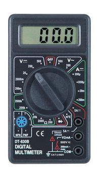
Turn the amp on and adjust the bias for each channel to desired setting. I have set mine at 12mV per channel. More than that will make the amplifier run hot and will require special considerations.
- Let the amp run for a few hours and check if the bias is still correct.
All done! Enjoy or continue reading my evaluation.
| 