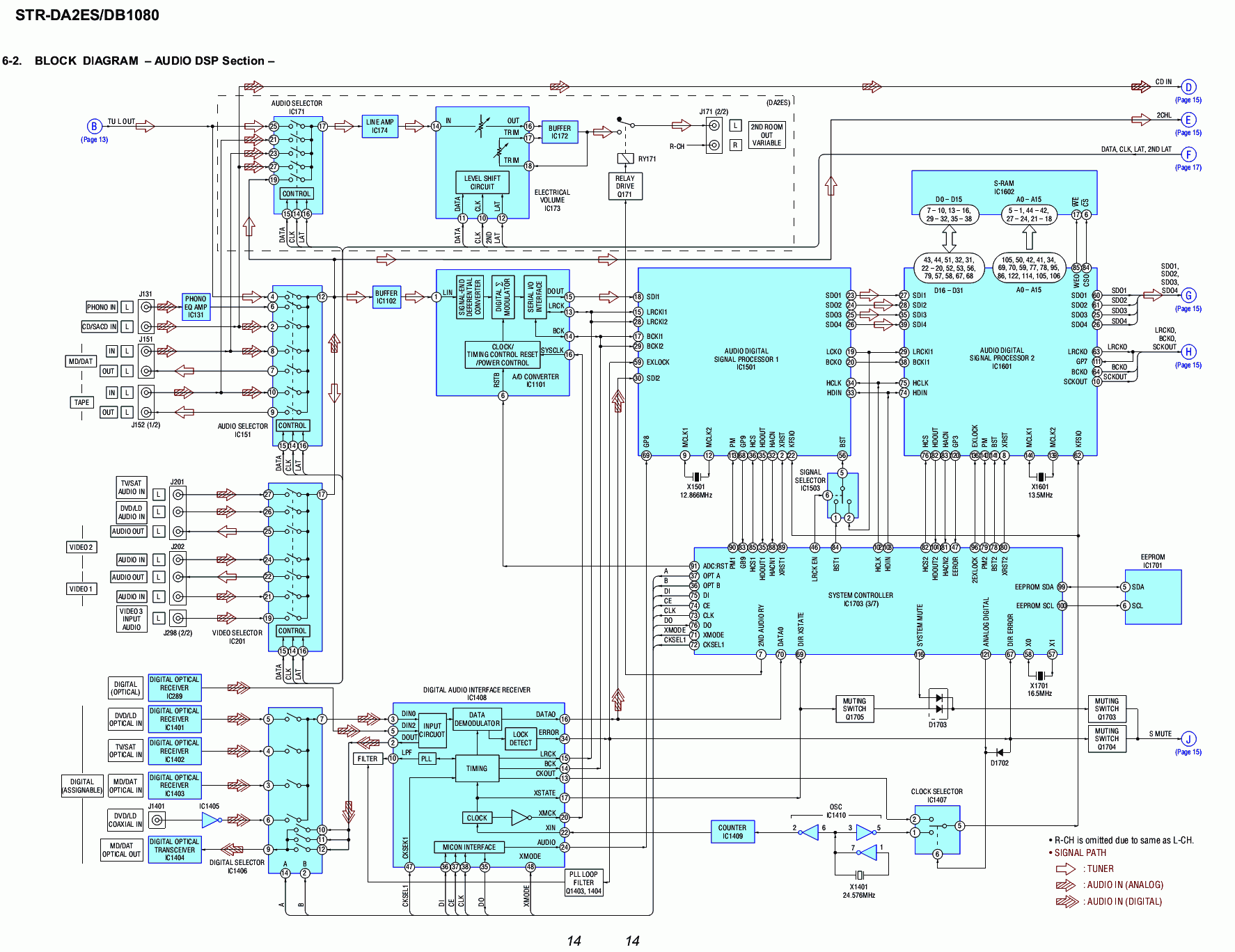
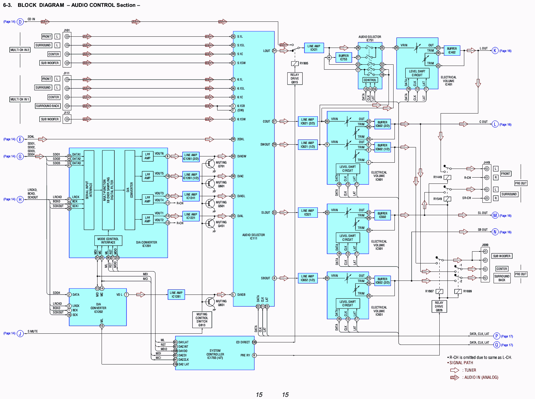
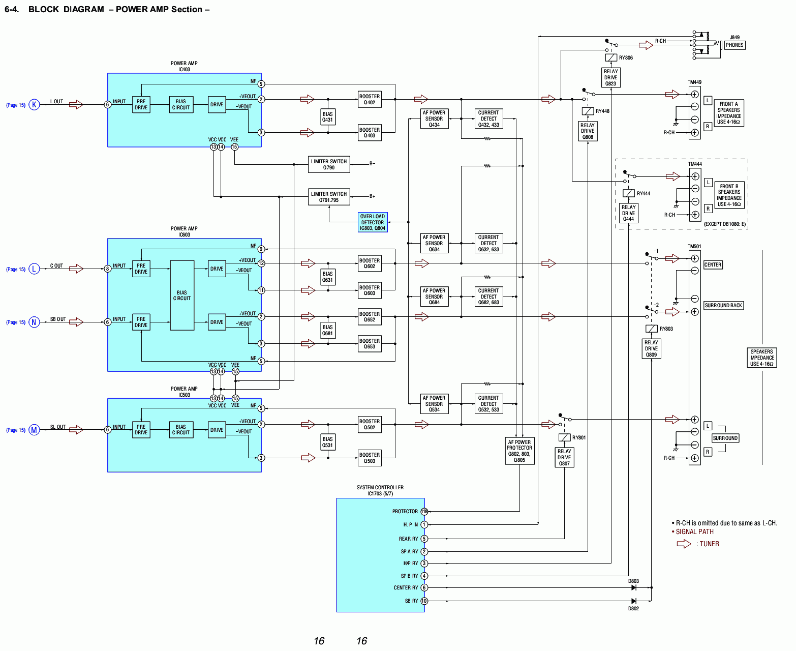
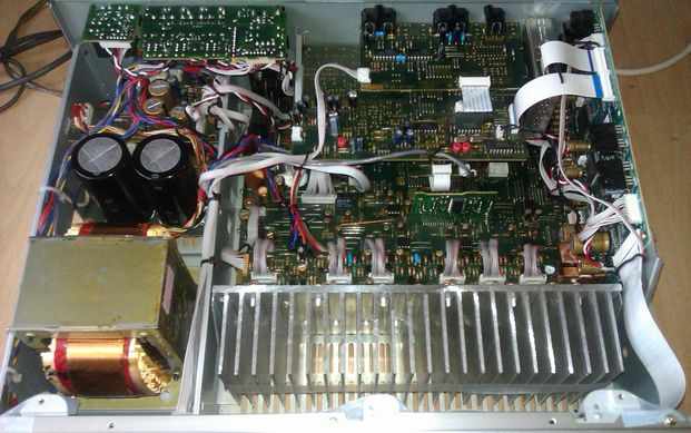
 To get a better understanding of the DB1080 we'll try to follow our signal trough the entire unit and how it is converted to sound. The service manual was easily found on the web and at hifi-engine. Lets look at the block diagrams first, we'll assume a digital stereo signal as input.
Audio DSPThe digital coax signal enters at bottom left en passes trough the following IC's:
This is quite interesting, already the signal has been touched or perhaps altered by 3 chips. The Sony chips are mysterious, no data is available at all for them. Obviously Sony doesn't want anyone to copy their designs. These chips do all of the surround decoding, if we want to know the impact of these chips we'll have to use the multi-channel direct input and listen for any differences. Audio ControlNow the signal becomes analog and will pass these IC's:
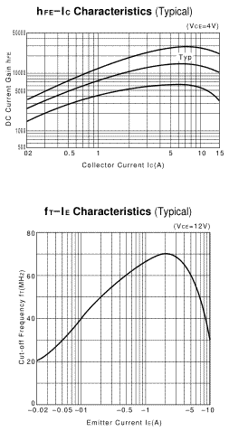
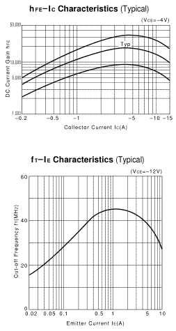
That's quite a stack of IC's our signal has to go trough. This is exactly the reason why it is much more difficult to get a surround receiver to perform like a simple stereo amp, the signal is touched so many times. In a simple stereo amp we would only have one mechanical potmeter and one preamp. I can't say a lot about the digital potentiometers and the audio switches, they are necessary and most likely will not harm the signal much. Digital switches and potentiometers consist of an array of transistors that open or close or an array of resistors. Measuring equipment at the time of design (2001 ish) only went as far as 4 figures so these probably perform better than the datasheet mentions. The DAC looks allright to me, but the op-amps got me worried. A single op-amp isn't alarming but if you are going to put four in a chain you better choose the op-amp carefully. A configuration like this will amplify any nasty characteristics 4 times. Think of an op-amp like a miniature amplifier and now put those in a chain of 4, see were i'm going with this? Would this influence the sound much? The M5281 is very old and in my opinion not worthy for a high-end device. Even the datasheet mentions the following and I quote: “The devices have virtually the same characteristics as the 4557, 4558, 4559 and 741 operational amplifiers.” This really puts things into perspective and if we look at the performance graph things don't improve either. 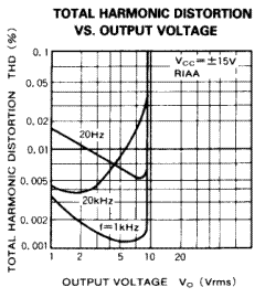 The NE5532 would have been a much better choice and valid for that time, see these 2 excellent reviews on this op-amp at EETimes and at nwavguy. It shows that even with a gain of 7 times distortion remains below the 0,001 mark. A note about the 5532: This op-amp is produced by different manufacturers of which strangely enough Fairchild performed best with only 0,0005 and Texas Instruments worst with 0,001 THD. Read about this here (in dutch). Power amplifierThe power stages are built around a Sony favourite chip, the uPD2581V. This chip is found in almost every Sony receiver from the late 90's trough most of the 00's.Integrated circuits like this greatly simplify an amplifier stage without compromising sound quality like a fully integrated amplifier module would do (for example an LM3886). In short each amplifier channel consists of one IC, a bias circuit and two output transistors. The output transistors are pair of 2SD2560+2SB1647, which are high gain darlington types. Usually I don't like darlington transistors but these are made by Sanken and specifically designed for audio purposes. The 2SD2560 and 2SB1647 are also high speed (70mhz):
This pair is quite well matched and should do fine. All in all good stuff, lets have a look at the bias circuit. Amplifier Bias circuitOn a typical stereo amplifier the bias can be adjusted trough a simple trimpot. This is the class A part of any class AB circuit. Since trimpots are not very precise devices they require regular inspection.Maintenance is impractical for surround receivers and for example car audio amplifiers, for this reason the bias is then usually fixed with a single resistor instead of a trimpot. To further reduce maintenance and increase lifetime the bias has also been reduced to the absolute minimum. The bias is quite important to AB type amplifiers because it determines how much distortion is present at low power output. Distortion for a typical AB type amplifier will look very similar to this curve: 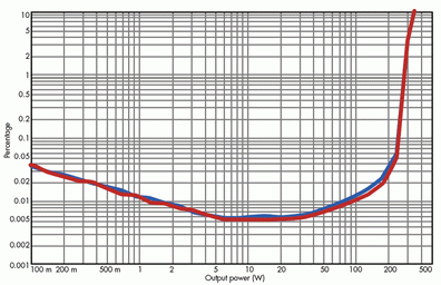 If you increase the quiescent current trough the bias you can reduce the amount of distortion at low output. This is even more important on surround receivers than regular stereo amplifiers because music is quite a constant load in respect to the signal, a movie on the other hand contains a lot of quiet and ambient parts which only create a small load on the amplifier. This means distortion will be higher. 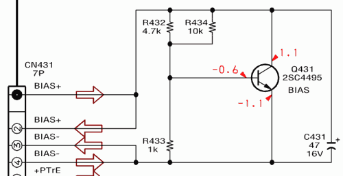 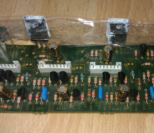 Conclusion |
Amplifiers > Sony STR-DB1080QS >

